Figure 1. Milling process
This spot facing should create a uniform seat.
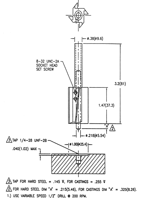
Figure 1 shows specifications for drilling and spot face grinding when mounting accelerometers using the stud mount method, and Figure 2 shows the correct and incorrect milling process.
Figure 2. Correct and incorrect milling
Note: Properly align the drill so that the tapped hole is perpendicular
to the mounting surface.
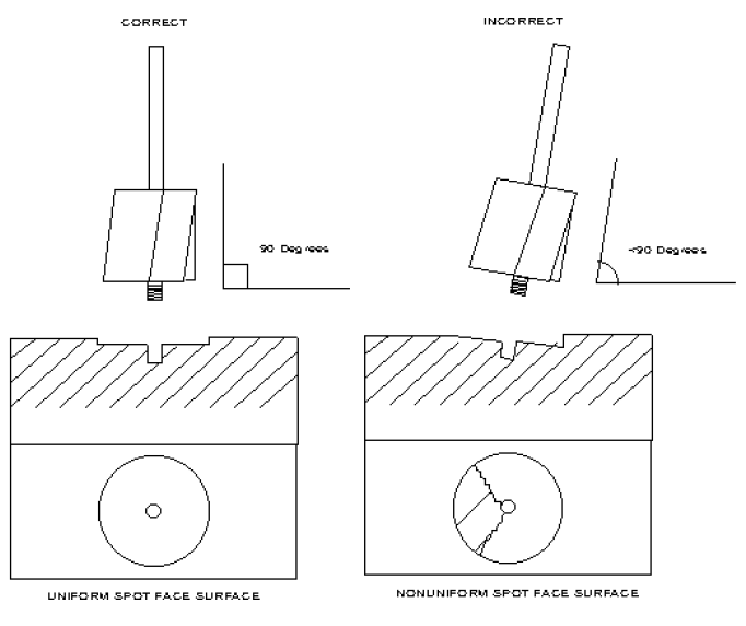
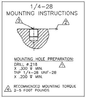
Figure 3 shows the specifications for drilling, tapping a pilot hole, and torqueing the mounting stud when mounting the sensor.
Figure 3. Accelerometer mounting