Overview
Warning: If the sensor is installed in a high-voltage
environment and a fault condition or installation error occurs, the sensor
leads and transmitter terminals could carry lethal voltages. Use extreme
caution when making contact with the leads and terminals.
Procedure
-
Attach the sensor leads. Follow the wiring diagram in
Figure 1 to
connect one sensor, the wiring diagram in
Figure 2
to connect two sensors, and the wiring diagram in
Figure 3
to connect one sensor with temperature.
Note: You can connect one or two accelerometers to the CSI 9420. You can connect only one accelerometer with a temperature sensor.
Figure 1. Connecting one sensor
- Connector 1 – red wire
- Connector 2 – white wire
- Connector 3 – blank
- Connector 4 – black wire
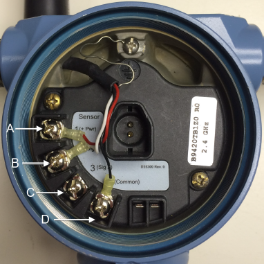
Figure 2. Connecting two sensors
- Connector 1 – two red wires, one from each accelerometer
- Connector 2 – white wire from one accelerometer
- Connector 3 – white wire from other accelerometer
- Connector 4 – two black wires, one from each accelerometer
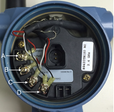
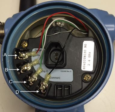
Figure 3. Connecting one sensor (accelerometer with temperature)
- Connector 1 – red wire
- Connector 2 – white wire
- Connector 3 – green wire (temperature wire)
- Connector 4 – black wire
Results
Note: You can use crimp-on ferrules or lugs to improve long-term
reliability of sensor wiring.