- LCD
- Field Communicator
- Smart Wireless Gateway
LCD
If the LCD is installed and enabled, it should display the measured values at the configured update rate during normal operation.
The front electronics end cap (the cap covering the LCD) is certified for Class I, Division I in appropriate gas environments (check the nameplate on the device for details).
Exposing the electronics to a production environment may allow particulates, moisture, and other airborne chemicals to enter into the device, which could lead to contamination and potential product performance issues. In all cases, whenever opening the front end cap, be sure to seal it completely afterwards by tightening until the black O-ring is no longer visible.
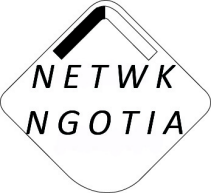
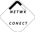
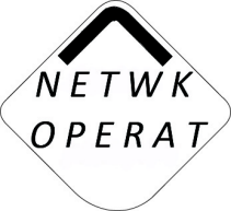
Table 1 shows the LCD screens when the CSI 9420 connects to a network.
| Searching for network | Joining the network | Connected to the network | Operational and ready to send data |
|---|---|---|---|

|
|
|
|
For more information on LCD screen messages, refer to LCD screen messages.
Field Communicator
You can verify the status of the CSI 9420 and configure it using a Field Communicator. Table Table 2 shows the fast key sequences you can use to configure and connect the CSI 9420 to a network. See the Configuration with a Field Communicator and Field Communicator fast key sequences for more information on the Field Communicator menu trees.
| Key sequence | Menu item |
|---|---|
| 2, 2, 1 (Manual setup) |
Network ID Broadcast Info Join Device to Network Configure Publishing Configure Update Rate Transmit Power Level Default Burst Config |
| 2, 1(Guided setup) |
Configure Sensors Configure Variable Mapping Configure Units Alert Limits Sensor Power Enable Join Device to Network Configure Publishing Configure Update Rate |
Smart Wireless Gateway
From the Smart Wireless Gateway web server, navigate to the Explorer page. This page shows if the device has joined the network and if it is communicating properly.
The Explorer page displays the transmitter tag name, PV, SV, TV, QV, time of last update, and update rate (burst rate). A green status indicator means that the device is working properly. A red indicator means there is a problem with either the device or its communication path.
Figure 1. Smart Wireless Gateway
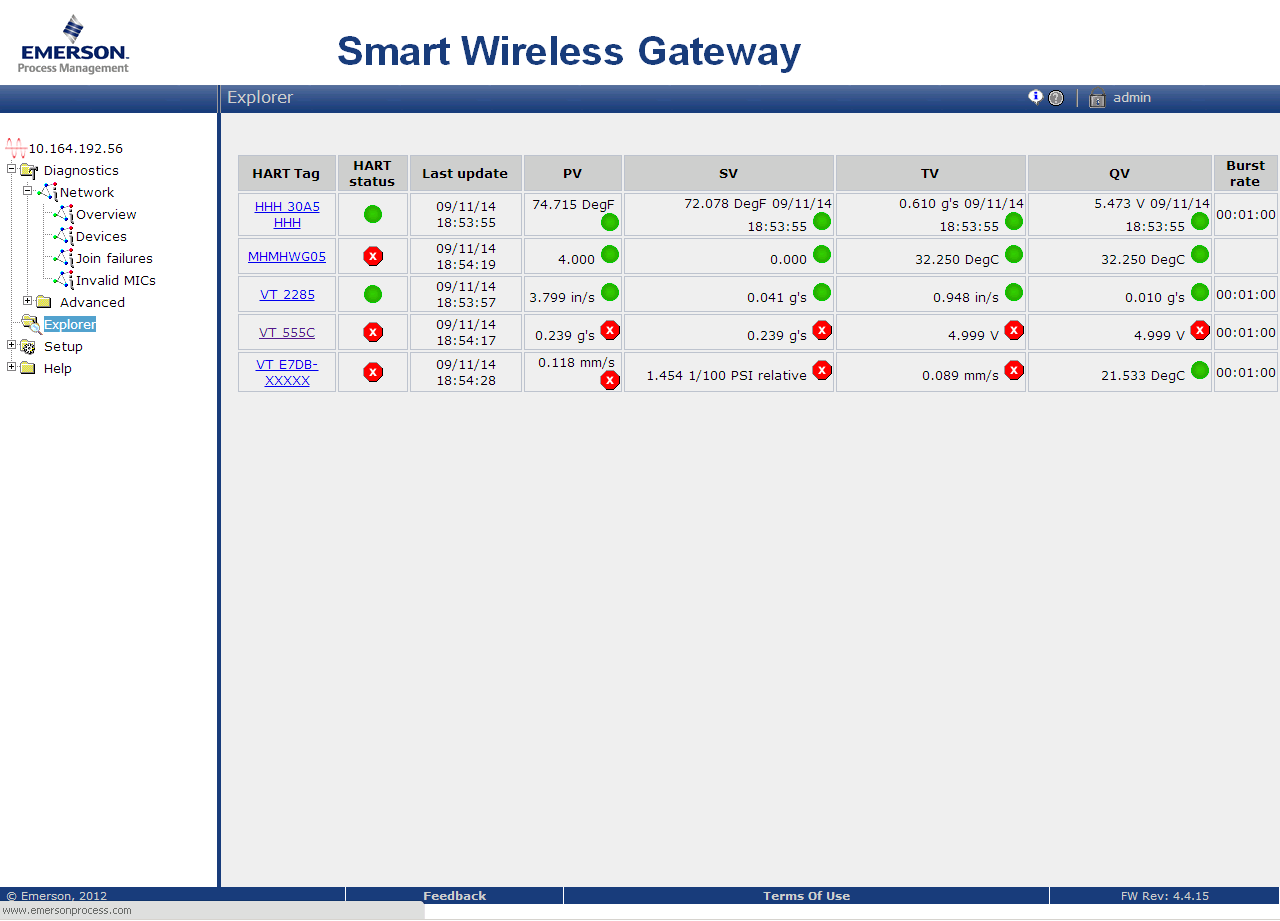
Click on a tag name to display more information about the device.
If the CSI 9420 is configured with the Network ID and Join Key, and sufficient time for network polling has passed, the transmitter will then be connected to the network.
The most common cause of incorrect operation is that the Network ID or Join Key are not set correctly in the device. The Network ID and Join Key in the device must match those found on the Smart Wireless Gateway. From the Smart Wireless Gateway, click to display the Network ID and Join Key. Make sure the setting for "Show join key" is set to Yes.