- Do not connect lead sets to the HART and HART + pwr terminals at the same time. If the lead sets are connected to devices, this increases the chance of wiring mistakes and could create a short in the HART loop.
- Do not add any external power to the device when the Trex unit is powering the device. This can blow a fuse inside the Trex unit. The repair/replacement will need to be completed at an authorized service center. Ensure the device is disconnected from the loop/segment and no other wires are connected to the device before providing power from the Trex unit.
- The Trex unit cannot power a 4-wire device. Do not connect Trex unit to the power terminals of a 4-wire device. This can blow a fuse inside the Trex unit. The repair/replacement will need to be completed at an authorized service center.
- Do not connect the mA terminals (ammeter) in parallel with a powered 4-20 mA current loop. Ammeters have low resistance. This can disrupt the loop and cause devices to report incorrect values or positioners to move unexpectedly.
- Do not connect the mA terminals on the Trex unit to a power supply that is not current limited to 250 mA. This can blow a fuse inside the Trex unit. The repair/replacement will need to be completed at an authorized service center.

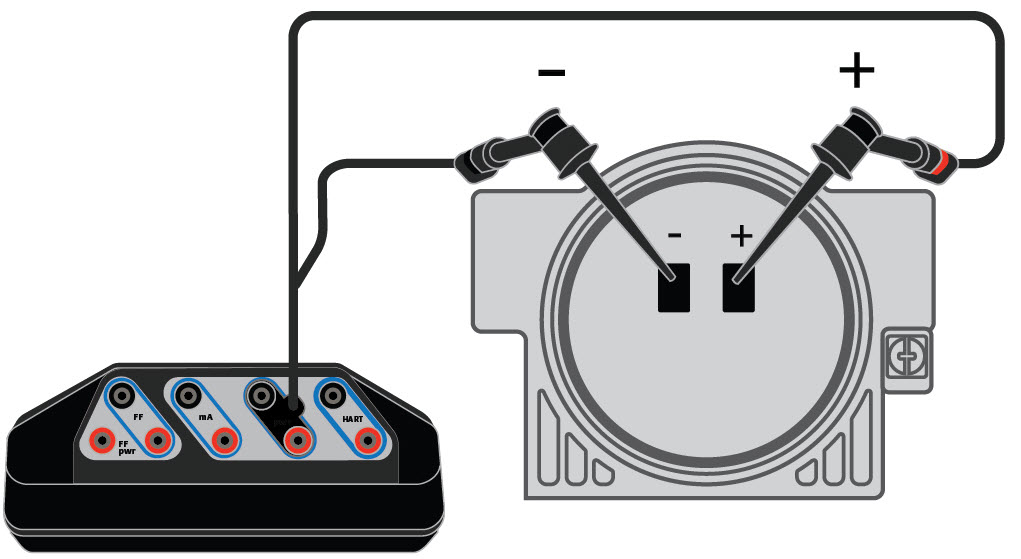
Power a HART transmitter
The Trex unit measures both voltage and current from the HART + pwr terminals. An internal 167 Ohm resistor is used when the Trex unit powers the device.
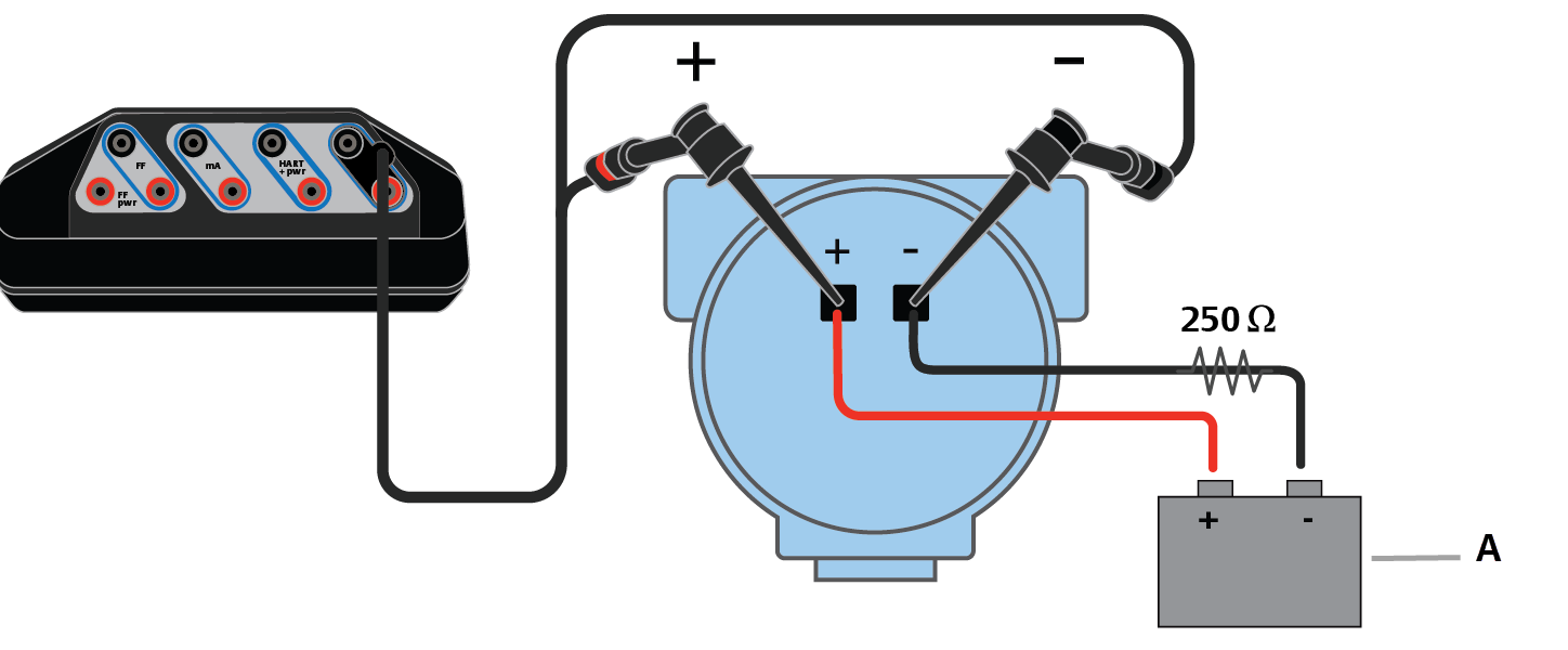
Measure voltage on an externally-powered HART transmitter
- Voltage source
Power and control current to a positioner
The Trex unit measures both voltage and current from the HART + pwr terminals.

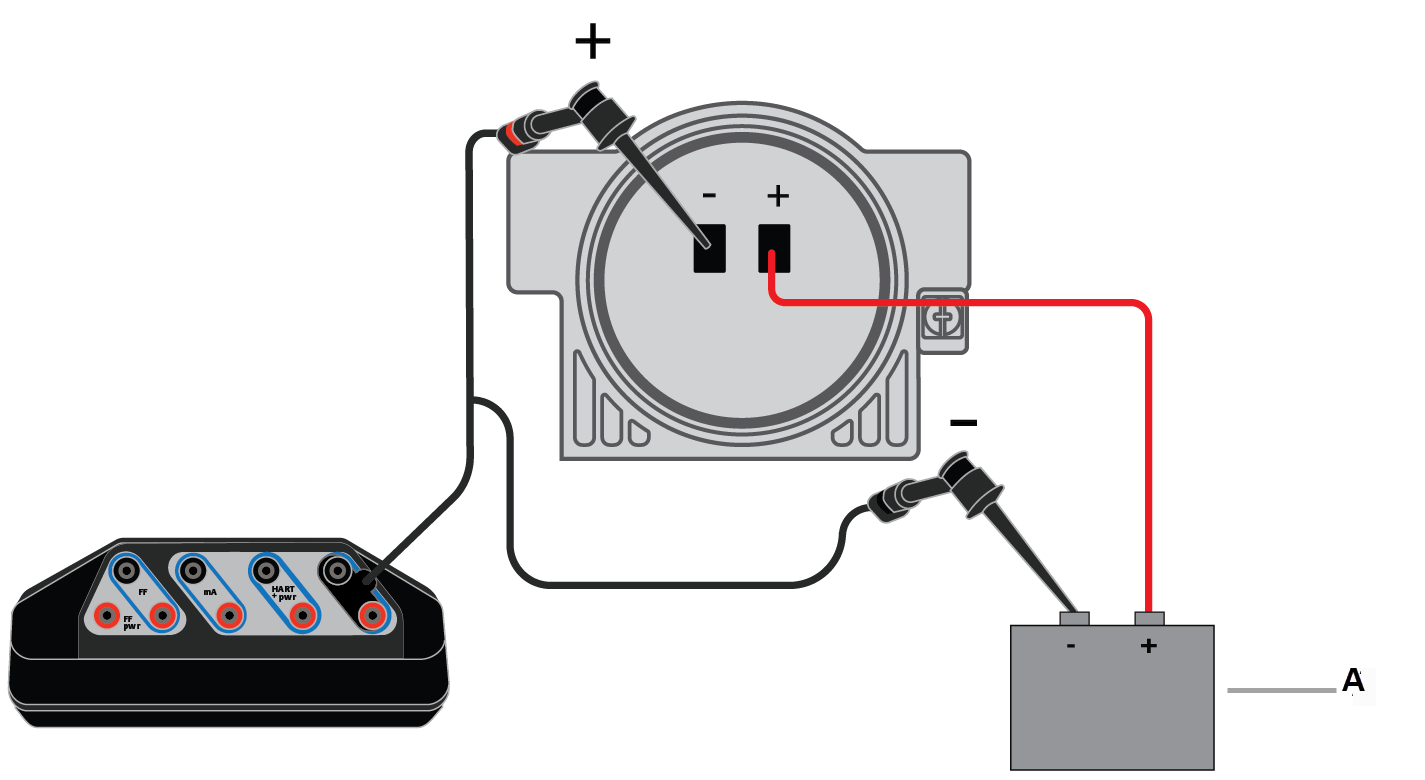
Connect to an externally-powered positioner in-parallel
The Trex unit measures voltage from the HART terminals. Voltage measurements can be taken at various points to identify voltage drops along the loop.
- Current source
Connect to an externally-powered positioner in-series
The Trex unit controls current from the HART terminals.
- Voltage source
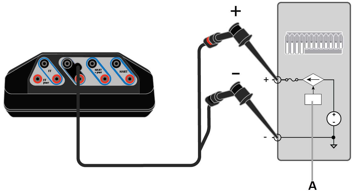
Control current to simulate a transmitter on an externally-powered loop
The Trex unit controls current from the HART terminals, which simulates a transmitter. The Trex unit controls current the same way as a transmitter controls current. The Trex unit is connected to the analog input (AI) channel.
You can connect the Trex unit at various points on the current loop, including a junction box, device connection point, etc.
- Analog input
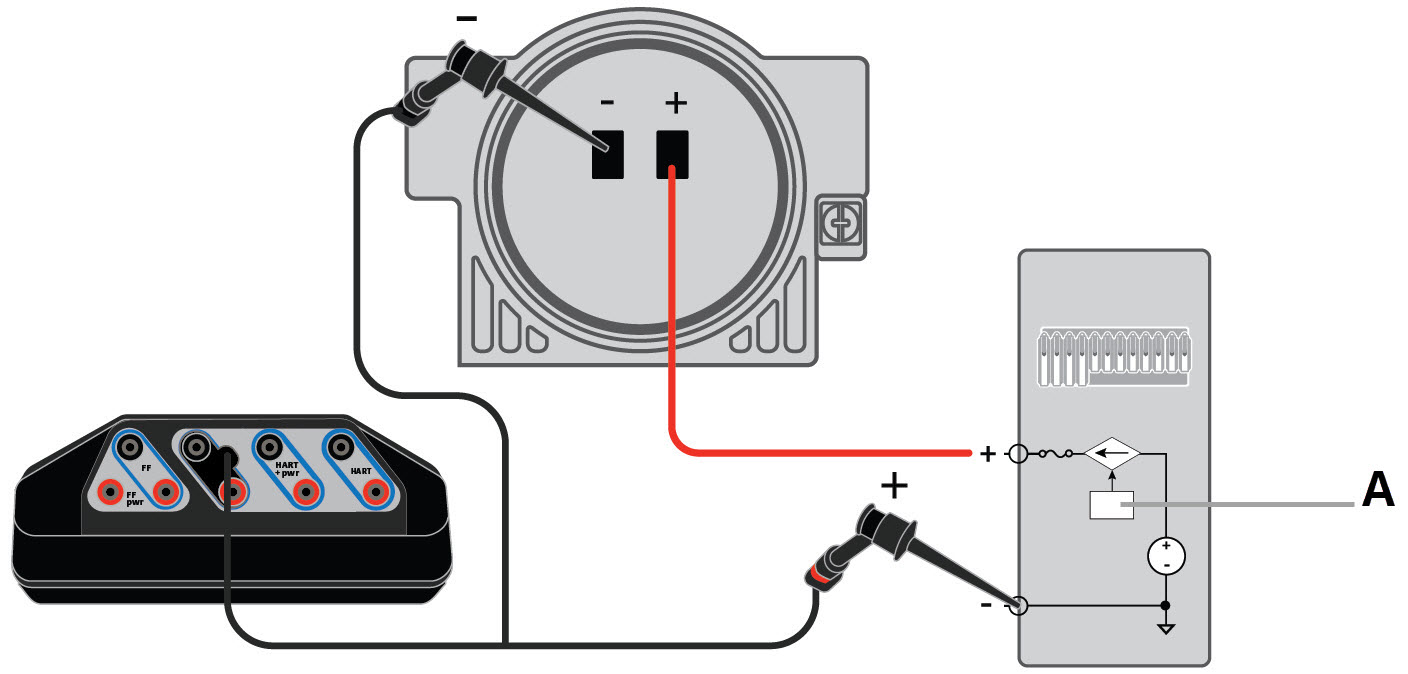
Read current for an analog output loop check
The Trex unit is connected to an analog output and is measuring current from the mA terminals. You can connect the Trex unit at various points on the current loop, including a junction box, device connection point, etc.
- Analog output
Connect to an externally-powered positioner and read current
- Analog output
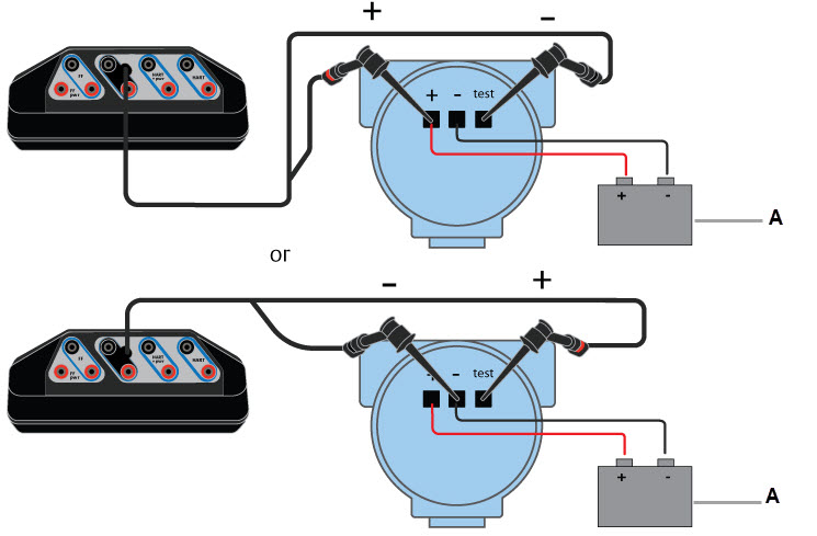
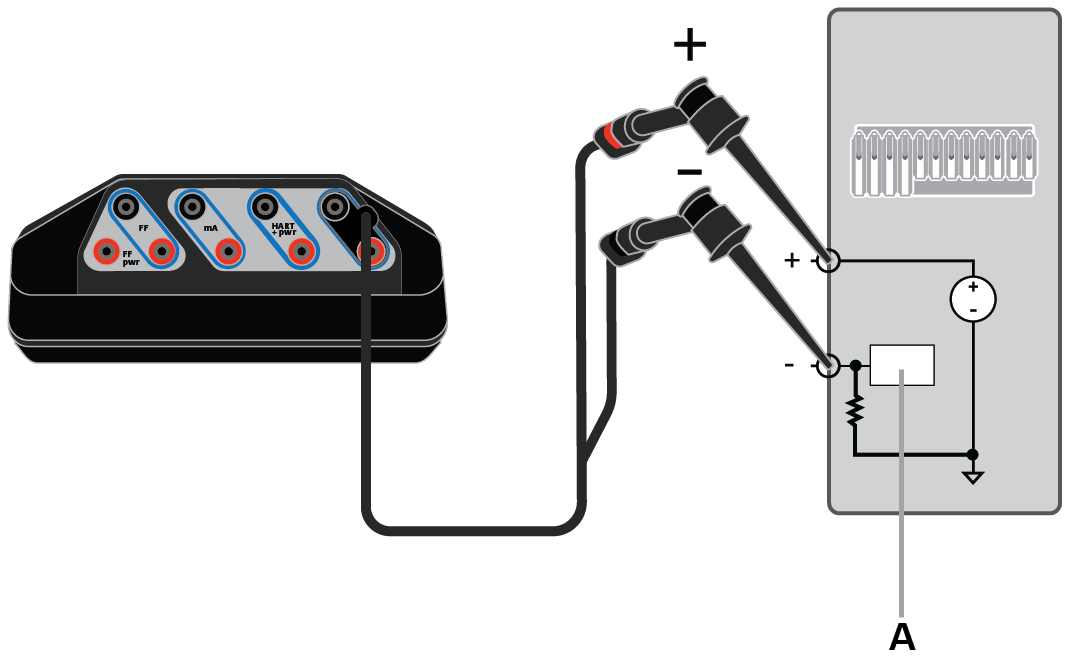
Measure current from an externally-powered transmitter device with test terminals
The Trex unit measures current from the mA terminals on an externally-powered loop without breaking the loop and connecting the ammeter (mA terminals) in-series.
- Voltage source
Power and control current to simulate a transmitter on an unpowered loop
- Analog input