Overview
Warning: While you can perform this modification for either
CSI 9420 devices that are certified as intrinsically safe, for non-rated CSI
9420 devices that carry no hazardous area certification, or for CSI 9420
devices that are certified as non-incendiary (e.g. Class I, Div 2 or Zone 2
rated), only an Emerson Product Service Center personnel should remove and
reinstall the LCD . Failure to do so may void the hazardous location
certification.
Figure 1. Installing the LCD
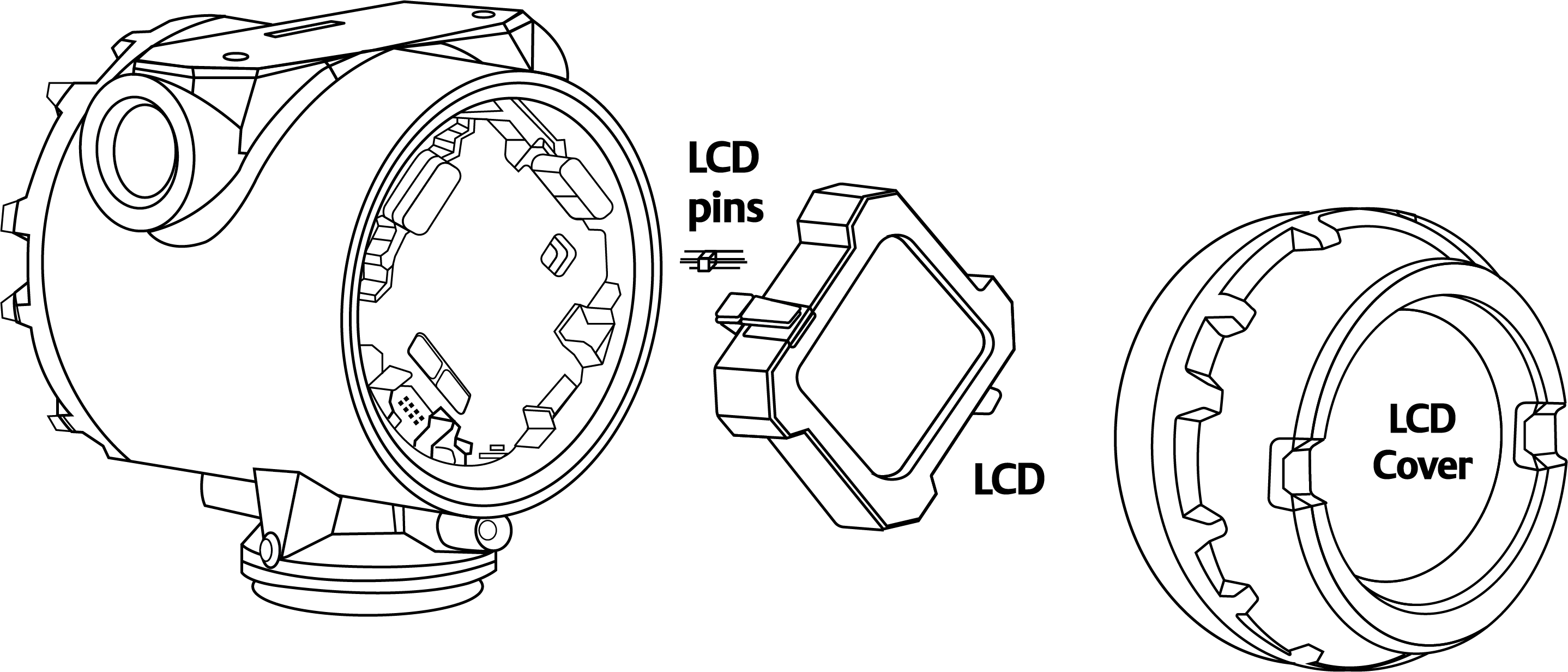
Procedure
-
Attach the LCD cover.
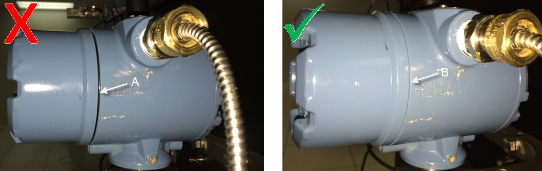
Use a strapping wrench to tighten the cover until it will no longer turn and the black O-ring is no longer visible.
Figure 2. Sealing the end cap
- Improperly sealed end cap. Black O-ring is still visible.
- Properly sealed end cap. Black O-ring is no longer visible.
 Important: Moving one LCD around to multiple devices, on an “as need” basis, is NOT recommended. This can cause reliability problems over time. The connector pins on the LCD are not designed for repeated connect/disconnect.